


CONSTRUCTION
 Having sorted out the basic design of the chassis - compensation arrangements, motor and gearbox etc, the next stage is to make the individual components. For the mainframes I use 18th nickel-silver, which is about scale thickness. I use nickel silver in preference to brass for all my scratchbuilding, principally because it is so much easier to solder than brass, and that’s because it doesn’t transmit heat as easily. I think it also takes paint better, but that’s not quite so clear. I either mark the outline of the frames directly onto the metal, or temporarily fix a section of the drawing onto the frames to use as a guide for cutting out. Whichever method is used, the cut-outs have to be carefully measured and cut accurately to match the wheel-base.
 The other key components at this stage are the bearings, hornguides, frame-spacers and coupling rods. The spacers are cut out of double sided copper-clad PCB. I use a standard width for frame spacers of 15mm (slightly under scale) but enough to give a bit extra sideplay to more easily negotiate curves. Gaps have to be cut into the copper to provide the insulation between the frames. I usually aim to cut the gaps about 3mm from each edge to leave enough strength for the soldered joint to the frame, and this leaves a neutral section in the middle of about 9mm, as shown in the photo.
Bearing and guide assemblies are available from a variety of suppliers, but some of these seem to me to be over designed, and unnecessarily complex. The photo shows simple versions - in this case bearings made on my lathe, and guides made on a milling machine. I have made the guides by hand in the past, but a milling machine is obviously much faster and more accurate. Like any machine, it takes a while to set up, but once done, enough guides can be made in a few minutes for several locos. Nickel silver is rather soft and doesn’t mill very cleanly, so a bit of work is required to finish them off.
Whatever system is used for the bearings, final fettling is likely to be required to make sure that bearings are a good sliding fit in the guides, with minimal slop. An essential part of this process is to pair up each bearing with a guide and mark each clearly, so that they don’t get mixed up at a later stage in the process.
The coupling rods illustrated are also made on a milling machine from mild steel blanks. The end results can be good, but this is not an easy process, so an alternative is to use one of the many versions offered commercially. An advantage of making the rods from steel is that the colour is right - nickel silver rods don’t look quite right to me. The rods shown have the joint in the proper place - ie not just as an overlap on the centre axle.
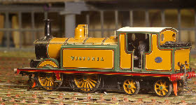
 The loco chassis illustrated here is for a ‘Brighton’ 0-6-2T E5. These engines used radial axle boxes, and these are perfectly feasible to replicate in model form. My first attempt was fabricated out of sheet metal, and was fairly crude, but it worked. When I moved onto split axle pick up, a metal axle box across the frames clearly wouldn’t work, so I experimented with perspex. Making a radial box taxes my mediocre skills on the lathe and milling machine, but the basic concept is to turn a ring of perspex (about 6x6mm cross-section, and minimum 80mm diameter for 4mm:ft), and then to cut this into sections, square off the ends to length, and drill an appropriate size hole through the middle, exactly parallel with the horizontal axis. The photo illustrates some of this. Perhaps I’ll add a more detailed description with photos next time I need to make one.


 Having sorted out the basic design of the chassis -
 The other key components at this stage are the bearings, hornguides, frame-
 The loco chassis illustrated here is for a ‘Brighton’ 0-